Installation Guidelines

Best practice for Installation of FIREMIKS

AI extended

SOME IMPORTANT INSTALLATION GUIDELINES

When installing FIREMIKS we strongly recommend that the concentrate tank minimum level is above the inlet of the dosing pump so that the concentrate has a free flow from the tank down to the dosing pump, this makes the suction efficient and immediate from the start. Gravity feed is a requirement when installing our piston pump type model - PP,

The internal diameter on the suction system must have an equal diameter, or one step larger, as the inlet of the Selector valve Dosing/Flushing valve on the dosing pump. Consult Data sheet for each model for detailed recommendations.

FIREMIKS is designed to operate with clean water. No abrasive particles should be present in the water flow. Attention! Rinse the piping thoroughly before installing FIREMIKS to ensure that the extinguishing water is completely clean of waste products after welding, etc.

Skärmbild 2025-06-24 162838

If the installation is to operate for an extended period of time with extinguishing water only, a by-pass with suitable valves should be installed around the FIREMIKS system to avoid unnecessary wear.

Dry running of the FIREMIKS dosing pump is not allowed, always use the internal flushing if suction of concentrate does not occur.

For fixed installations we recommend that FIRMIKS is delivered with a Dosing Return Valve (DRV) that makes it possible to return extinguishing media to the tank. This enables simple, fast and regular testing of the device’s functionality, including the ability to check the proportioning without wasting any concentrate.

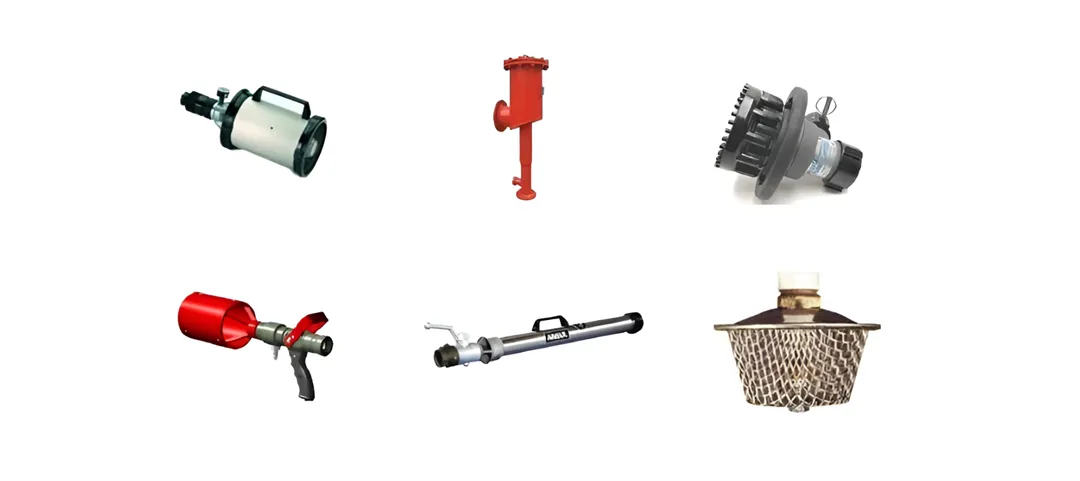
WORKS WITH ALL COMMON NOZZLES

FIREMIKS works with all common types of nozzles, among others: Low-Ex, Medium-Ex and High-Ex nozzles, foam sprinkler heads, spray nozzles, foam monitors and foam chambers.
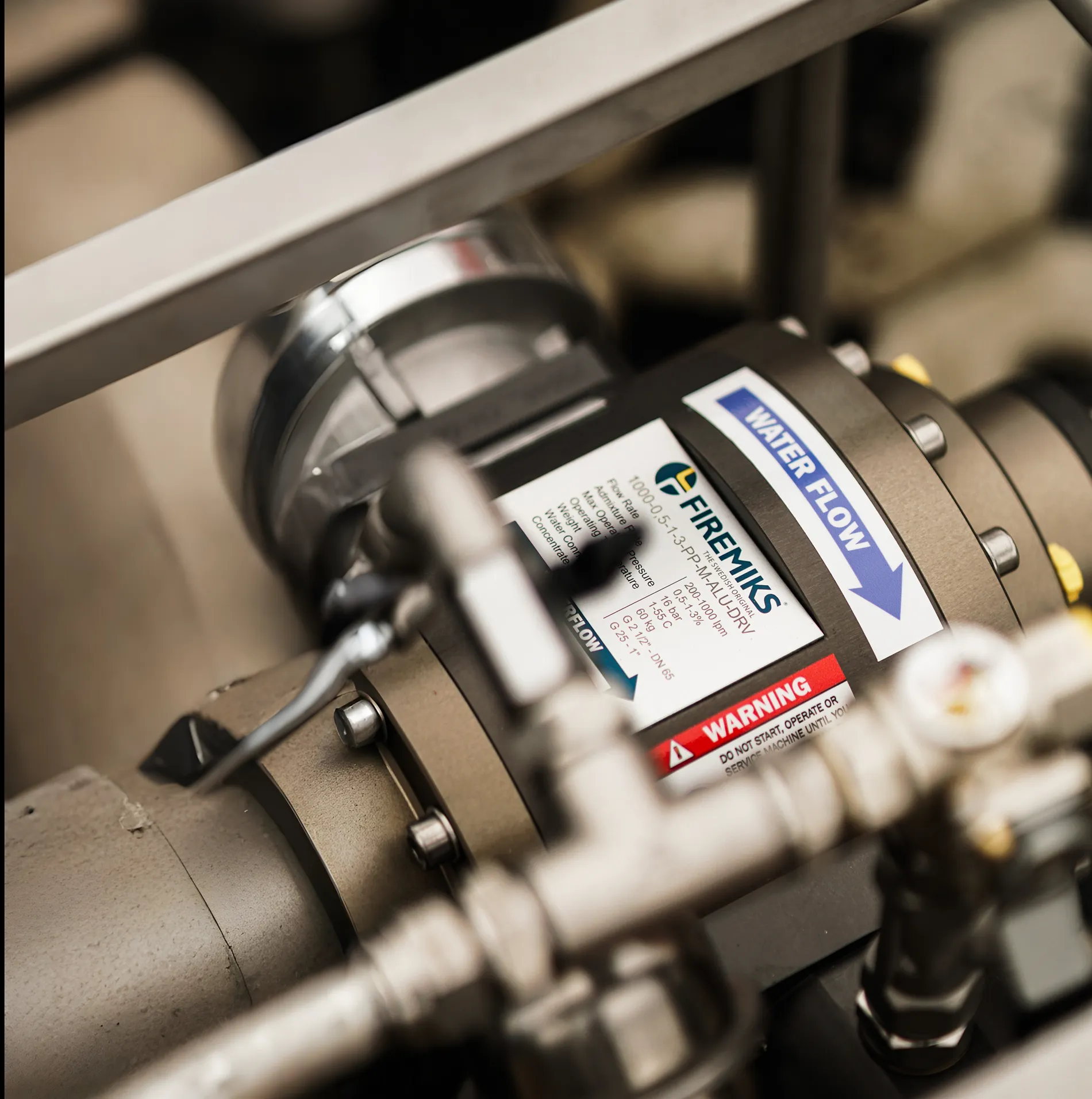
The proportioning does not change based on the nozzle used, e.g. FM Approval of FIREMIKS is independent on the rest of the system - the whole protection system does not need to be approved as a whole.

You will find further information and documents, such as our Instruction Manual, Data sheet and Flow Chart on our Download page.

Do not hesitate to contact us on info@firemiks.com for more information!

89

PARALLEL INSTALLATION

Above picture show an example of a parallel installation. Most important is to design the piping so that the flow is divided evenly between the two units. Consult us for our support if you consider this solution.

687232_720_1000_1_0-Picsart-AiImageEnhancer

We also offer our units to be installed in parallel on a basic skid without piping to double the flow capacity. For example, above FIREMIKS 16000-3-PP-F-SKID (2 x 8000-3-PP-F).

716797_720_1000_1_0-Picsart-AiImageEnhancer
Cookies

This website uses cookiesfor statistics and user experience.

This website uses cookies to improve your user experience, to provide a basis for improvement and further development of the website and to be able to direct more relevant offers to you.

Feel free to read our privacy policy. If you agree to our use, choose Accept all. If you want to change your choice afterwards, you will find that option at the bottom of the page.